
Fume Extractor
Small project I made to test my knowledge in electronics. It's a mini 5V fume extractor made to be used when soldering.
Overview #
The idea was to make the fume extractor so I wouldn't breathe the fumes from the solder. So I started a small project with a Potentiometer and a small 6cm 5V DC brushless fan.
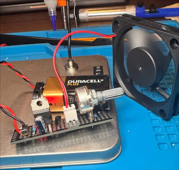
The initial version was supposed to use a 6cm fan, however I realized that a 6cm fan would do absolutely nothing if it stood too far from the smoke, which is almost all the time. So I changed the build to a 12cm one. It's still a 5V fan, so nothing really changed in the circuit in V1 or V2 other than the size.
V3 though, this will be different. I am planning for a switching converter with a rechargeable 9V Li-Ion battery.
Initial Design #
After I tested it in the breadboard, I put a schematic in KiCAD to help me draw a PCB for it:
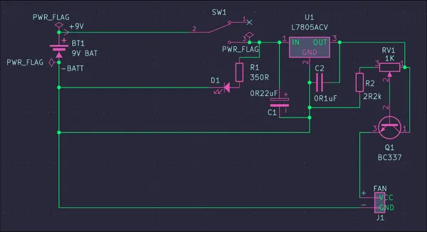
I opted to have the fan in a Molex (J) connector because it would be easier if I needed to swap the fan for a bigger one later on, which is what I am planning to do with a 9V/12cm fan, this was basically the test.
This was V0, the next step was to complete it in the perfboard, which I did (as the photo shows). I wasn't planning on going any further with this.
V1 #
Once I realized that the perfboard was crap, I ordered a set of 5 PCBs from PCBWay, same circuit, just in a PCB so I didn't have to use the board. The whole thing is in the KiCad project. Then I wanted to make this a real thing. With a case and so on.
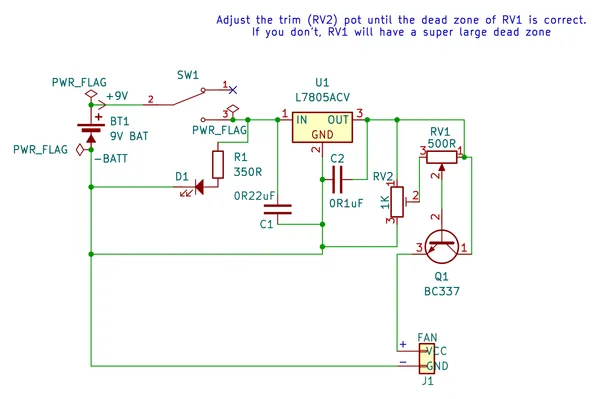
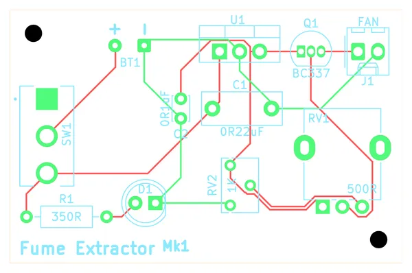
The final printed PCB was ok, but I learned some things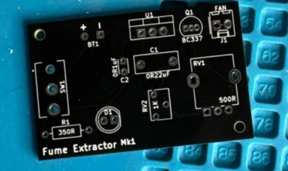
V2 #
Once I realized that I could make that circuit way smaller, I begin to work on what's the current version of the KiCad project. It's roughly the same circuit, the main differente is that it uses a molex connector both for the battery and for the fan. The LED is a 3mm one, and the orientations are corrected (as well as the blueprints. I made sure of that).
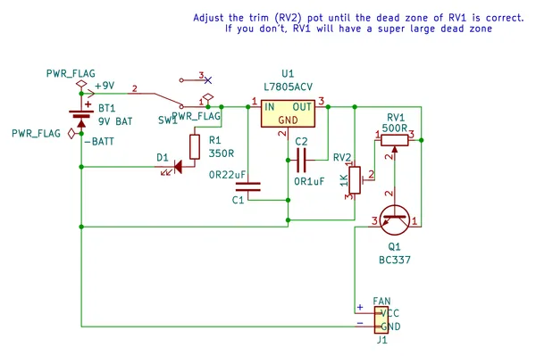
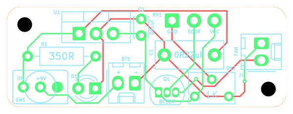
When I printed, it came back super cute 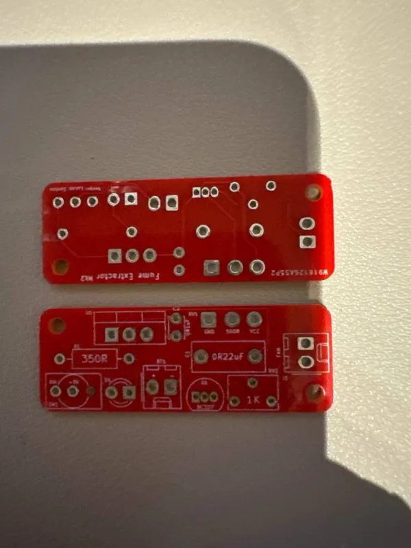
I also fixed the right-angled corners, which hurt like hell. However they got me less space to hold the board. But the space reduction was insane:
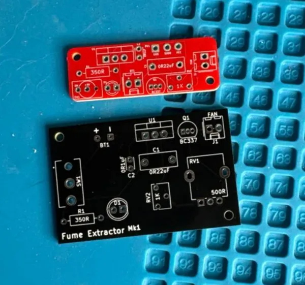
Also, the red color allows for a better view of the parts. Although I didn't complete the soldering of this one, I think I could've done better by putting the resistors and the capacitors in vertical positions. Maybe even soldering the capacitor on the back side.
The soldered version of it is quite interesting, it's way smaller and I think I can make it even smaller, for example, this is the final build:
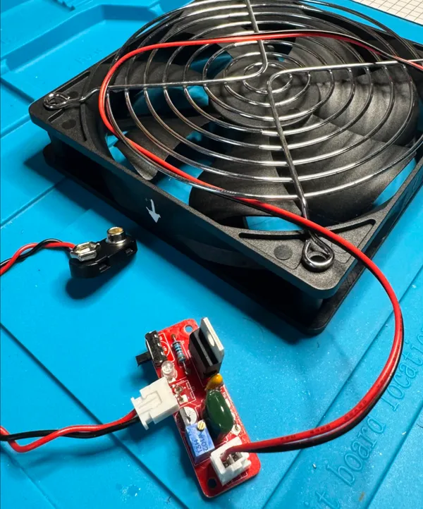
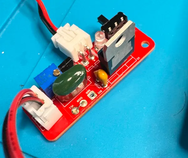
Here I removed the potentiometer in the back side of the Polyester cap, I did a small hack using a component leg from one of the caps to bridge the wiper to the VCC here
Bill of materials (v1, v2) #
| Part | Value | Qty | Notes |
|---|---|---|---|
| Resistor | 330R | 1 | For the LED |
| Trimmer | 1K | 1 | Just so the pot doesn't have a lot of dead room in GND. If you have a smaller pot this might not be needed. Single turn should be enough, multi turn is ok too because it allows for fine tunning |
| Switch | SPST or SPDT | 1 | |
| LED | 5mm red (3mm for v2) | 1 | |
| Battery holder | 9V, with leads | 1 | This will go into a Molex J connector |
| Capacitor | 0.1uF (100nF) | 1 | Any cap, ceramic works too. If the cap is electrolytic, the negative should be to GND |
| Capacitor | 0.22uF (220nF) | 1 | |
| Voltage regulator | LM7805 | 1 | Depends on the fan's voltage. A 9V or bigger fan runs straight from the battery. A 5V fan needs an LM7805 (not the 78L05, which is for low current) |
| Potentiometer | 1K (or less), linear | 1 | 500 seems to be a good place, but you can fine tune with the 1k Trimpot |
| Transistor | BC337 | 1 | |
| Fan | 12cm, 5V DC brushless | 1 | Also in a Molex connector |
V3 #
Version 3 is still to come. The idea is a bit ambitious:
- Make it even smaller with SMD components
- Replace the power regulator by a switching regulator IC based on a NE555 timing circuit, which is more efficient, and I lose less with the Dropout Voltage since the 7805 needs at least 2V more than the output to be able to run, and my fan needs at least 2.7V, so if I run it through an USB cable, I can't power the fan.
- Add a rechargeable Li Ion battery that can be charged through a USB port (USB-C would be the best)
- Being able to run it directly through the USB port is also a good idea
- Remove the potentiometers because it makes no sense to have a "half step" fume extractor, so it would turn on or off only.
- Try to add a smoke detector so I don't have to turn it on manually, and can keep it on
- And figure out a way to not drain the entire battery while keeping this thing on
Build log #
- 2026-06-28: Built it on a Perfboard. It "works"… But I can't really trust, the perfboard is bad because you need to stick solder into it but it will not stick!
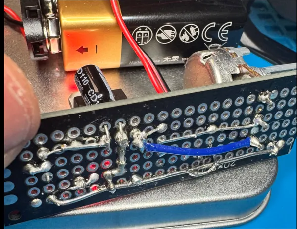
- 2026-06-30: I desoldered everything, it was very bad. I will re-do it this again.
- 2026-07-13: I ordered an actual PCB for it, the project files are on my Github project for it.
- 2026-08-02: The original board worked quite ok, I didn't take any pictures of it soldered ready, but I will soon make a v2 with all the other stuff
- 2026-08-10: V2 was made, but I shouldn't have ordered that, I already have ideas for a V3, should have just done the whole thing.
- 2026-10-12: I don't have a new version yet, but I am working on the case, which will dictate the size I can have for it.
- 2026-10-13: Decided to solder the second version of the board to use it while the V3 is not here
Lessons learned #
- Perfboards are terrible because I cannot stick the solder to it, never do again.
From v1 #
- Square PCBs hurt
- Always check the footprints. My switch was from a different brand and a different footprint than the big SW1 you see in the left side, I had to ignore it
- Always check orientations, the molex J connector is upside down.
- There's always space to make it smaller
- Black is not really nice to solder on top of
From v2 #
- Usually the problem is not the size, you can make it smaller, it gets more difficult to make, but it won't make your circuit better. What really made this board great was the form-factor
- M3 screws are better than M2 for positioning
- Square components don't really sit well in rounded corners
Next #
- Complete the V3
- Design the enclosure in a way that I can fit on a multiboard base and also make it portable
- Re-do the build.