
< projects
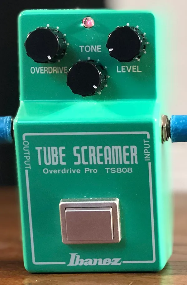
Ibanez Tube Screamer DIY
DIY build of the Ibanez TS808 Tube Screamer, one of the most iconic overdrive pedals ever made.
Overview #
The TS808 Tube Screamer is the overdrive Ibanez released around 1979, built by Maxon (Nisshin Onpa). Its mid-hump tone and soft clipping around the JRC4558 op-amp made it one of the most copied circuits in pedal history. This build follows the original TS808 values.
Design #
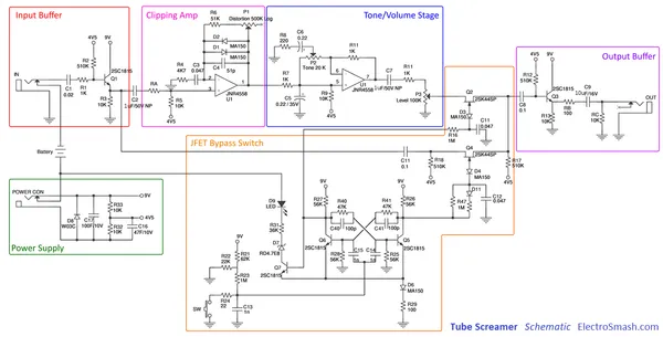
[!quote] Source Schematic and circuit analysis from ElectroSmash - Tube Screamer Analysis.
The circuit has four stages:
- Input buffer: a transistor stage that isolates the guitar from the rest of the circuit.
- Clipping amplifier: the op-amp boosts the signal, and the two diodes (D1, D2) in its feedback loop round off the peaks. This is where the overdrive comes from, and the "tube" part of the drive, because a digital drive would square the waves, and having it rounded would "mimic" an Electron tube
- Tone control: a filter around the second half of the op-amp, set by the Tone pot (P2).
- Output buffer: a second transistor stage followed by the Level pot (P3).
Bill of materials #
| Ref | Part | Value | Type | Substitutes | Source |
|---|---|---|---|---|---|
| D1, D2 | Diode | 1N4148 | Signal | 1N914, MA150 | |
| D8 | Diode | 1N4001 | Rectifier | W03C | |
| Q1, Q3 | Transistor | 2N5089 | NPN | 2SC1815, MPSA18 | |
| Op-amp | RC4558 | Dual op-amp | JRC4558, RC4559 | ||
| C17 | Capacitor | 100µF | Electrolytic, 10V | ||
| C16 | Capacitor | 47µF | Electrolytic, 10V | ||
| C9 | Capacitor | 10µF | Electrolytic, 16V | ||
| C2, C7 | Capacitor | 1µF | Non-polarized, 50V | Film | |
| C5, C6 | Capacitor | 0.22µF | Film | ||
| C8 | Capacitor | 0.1µF | Film | ||
| C3 | Capacitor | 0.047µF | Film | ||
| C1 | Capacitor | 0.02µF | Film | 22nF | |
| C4 | Capacitor | 51pF | Ceramic | 56pF | |
| RA | Resistor | 0Ω | Jumper | ||
| RB | Resistor | 100 | |||
| R10 | Resistor | 220 | |||
| R1, R8, R11, R12 | Resistor | 1K | |||
| R4 | Resistor | 4K7 | |||
| R3, R5, R9, R14, RC, R32, R33 | Resistor | 10K | |||
| R6 | Resistor | 51K | |||
| R2, R13 | Resistor | 510K | |||
| P1 | Potentiometer | 500K | Log (Drive) | 470K | |
| P2 | Potentiometer | 20K | Linear (Tone) | 22K | |
| P3 | Potentiometer | 100K | Linear (Level) | ||
| Footswitch | 3PDT | ||||
| Jack | 6.35mm | Chassis, stereo | Electrokit | ||
| Jack | 6.35mm | Chassis, mono | Stereo jack | Electrokit | |
| DC jack | 2.5/5.5mm | Chassis | Electrokit | ||
| Battery clip | 9V | Electrokit |
Build log #
- 2026-05-24: Collected the schematic and the bill of materials.
Lessons learned #
Still didn't build this. So for now, I just learned that the circuitry for a normal overdrive is not that simple.
Next #
- Swap the output section to TS9 values and compare.
- Try other clipping diodes (LEDs, germanium) in place of D1 and D2.
- Try to add an EQ pot for bass and treble