
Element Audio Buck Converters
Two LM2596 buck converters with added protection, in 3D-printed enclosures, powering my pedalboard.
Overview #
Two buck converters that power my Lekato Pedalboard, each one in its own 3D-printed enclosure. My goal with this was to make something that feels professional at home. I added those because the pedalboard has two outputs that output 12 and 18V and I needed to convert them down to 9V to be able to use all the outputs.
The enclosure has one side with a male connector to plug into my pedalboard, on the other side there's a female jack to connect the pedal.
Design #
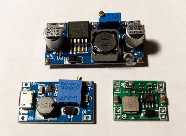
The base is an LM2596 DC-DC Buck Converter module, an adjustable step-down regulator 3.2-46V in, 1.25-35V out, 3A. The module already comes with a 100µF capacitor on both ends which protects against spikes, a toroidal inductor with a Schottky diode, and an LED so I didn't have to build the whole "is it on" thing. The inductor and the diode are what make the converter work: while the regulator's switch is on, the inductor stores energy, and while it's off, the inductor keeps the current going through the diode, so the output gets a steady voltage instead of pulses. But the issue is that the converter is super dumb, so I had to make some changes. I added:
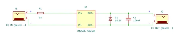
- 1A fuse at the input, against over-current. So it doesn't burn the converter and everything catch fire
- Ferrite bead against noise and humming
- 10.5V zener diode in reverse bias at the output, as over-voltage protection. Basically, if the trimmer pot dies or something, it would send the full input to the output so, in this case, the Zener would open and the voltage would flow back to the input, in theory creating a circuit breaker.
- 100nF ceramic capacitor in parallel with the zener, to prevent signal interference.
I am thinking if I should add a bigger Electrolytic Capacitor, maybe 250uF or 100uF to smooth the signal a bit more, but I think this might not be needed.
Both jacks are center negative so when I connect, I have to connect it reversed on the Input, because the buck converter module expects a center positive input, so the sleeve goes to the positive side (which would be the reverse of an expected center positive jack). On the output, the zener and the cap are wired across OUT+ and OUTin parallel, with the zener's cathode on OUT+.
And then the output needs to wire the center to the negative side, with the hot signal on the sleeve.
The enclosure is printed on my Bambu Lab A1 Mini. The front has a triangle pattern and the name of my brand. The converter is screwed to the inside, with room for heat-set inserts.
Bill of materials #
Per converter, I built two.
| Part | Value | Qty | Notes |
|---|---|---|---|
| Buck converter | LM2596 module, 3A | 1 | Idota, bought as a 10-pack |
| Fuse | 1A | 1 | Input, over-current protection |
| Ferrite bead | 1 | Noise filtering | |
| Zener diode | 10.5V | 1 | Reverse-biased at the output, over-voltage protection |
| Ceramic capacitor | 100nF | 1 | Parallel with the zener, against signal interference |
| DC input jack | Center negative | 1 | Sleeve (+) through the fuse to IN+, center (-) to IN- |
| DC output jack | Center negative | 1 | |
| Enclosure | 3D printed | 1 | Body, lid and screws |
Build log #
- 2026-09-14: Bought a 10-pack of LM2596 modules.
- 2026-09-15: Tested two converters while making the pedalboard cables. They're tiny, the fuse and the output jack are bigger than the converter itself. Planned the extra protection: fuse, ferrite bead, zener and ceramic cap.
- 2026-09-28: Electronics almost done, the enclosures were still missing.
- 2026-10-04: Printed the first casings. They came out a bit crooked.
- 2026-10-05: Made and printed a version 2.
- 2026-10-07: Finished, after about 5 iterations of the enclosure.
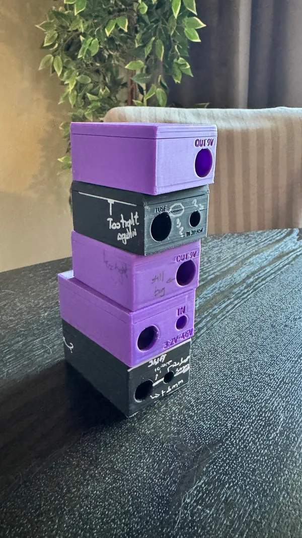
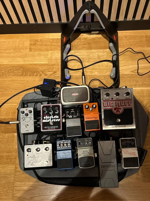
- 2026-10-09: The pedalboard is fully working with them. They're on the top side, and I think the wires are too short.
Lessons learned #
- The first enclosure failed because the lid ended up really loose.
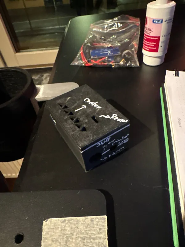
- For the next ones I reduced the final size and changed the layer height to 0.16 mm instead of 0.2. I tried 0.08 too but it became too thin and ended up with several imperfections, so 0.16 is ideal.
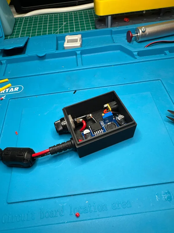
- The fuse and the jack needed to be off center because they got in the way, I haven't had thought of that
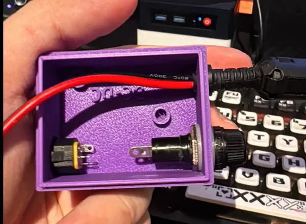
- Positioning the converter inside, on the screws, was the hardest part. I need the screw position plus an extra side for the heat-set inserts. Even though I measured where each converter had its screw holes, one of them was always off by something.
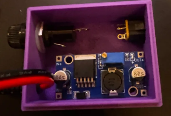
- Once closed I wanted the LED to be visible, which kinda happened but I wanted more visibility to that, also you can see that the text is not very visible too on the lid
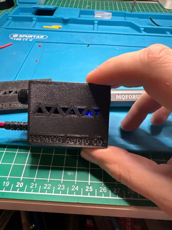
- In other colors, for example, I could make the brand name way better

- I actually came to the name I wanted to go with my pedal company if I ever make one. "Element Audio Co." has a nice name.
- Holes in 3D printing are terrible, and positioning something freehand is too. I still haven't figured out how the hell I will position the board in it, I will probably make the hole longer
- If I were to make more, I'd do it a little different. Probably with a longer input cable I still have 8 left so I can try to fix those, but I honestly have no need for it